ABS wheel speed sensor symptoms can point to a failed sensor, but they can also be caused by damaged wiring, corrosion at the mounting point, excessive wheel-bearing play, or a defective tone ring or magnetic encoder. Replacing the sensor before confirming the cause often leads to a warning light that returns after the first drive.
This guide explains how professional technicians separate an actual sensor failure from the other faults that can produce the same ABS, traction-control, or stability-control warning. The process applies broadly across passenger vehicles, but exact test values, wiring diagrams, tightening torques, and repair procedures must always come from the vehicle manufacturer.
What Does an ABS Wheel Speed Sensor Do?
A wheel speed sensor measures the rotational speed of an individual wheel and sends that information to the ABS control unit. The control unit compares signals from all four wheels. During braking, it can detect when one wheel is slowing much faster than the others and regulate hydraulic pressure to reduce the risk of lock-up.
The same information is commonly shared with traction control, electronic stability control, hill-start assistance, adaptive cruise control, transmission logic, and other systems. That is why one poor wheel-speed signal can illuminate several warning lights or disable functions that appear unrelated to the sensor itself.
Common ABS Wheel Speed Sensor Symptoms
The most common symptom is an illuminated ABS warning light. Depending on the vehicle, the traction-control or stability-control light may also remain on. Other complaints can include incorrect ABS activation at low speed, a disabled cruise-control function, a speedometer problem on some applications, or a stored wheel-speed-related diagnostic trouble code.
Symptoms may be constant or intermittent. A broken conductor inside the cable can reconnect as the steering or suspension moves. Corrosion can change the sensor-to-encoder air gap. A cracked tone ring may produce a repeatable signal drop once per wheel revolution. These different faults can all be described by a scan tool as a signal that is missing, implausible, intermittent, or outside the expected range.
| Observed symptom | Possible fault area | Useful next check |
|---|---|---|
| One wheel reads zero at all speeds | Open circuit, no supply, disconnected sensor, failed sensor | Inspect the connector and cable, then test supply and signal according to the wiring diagram |
| Signal drops out when steering or over bumps | Chafed cable, internal wire break, loose connector or poor routing | Monitor live data while carefully moving the harness and suspension through its normal range |
| False ABS activation near a stop | Weak or irregular signal, excessive air gap, corrosion, damaged encoder | Compare low-speed data and inspect the sensor seat, bearing, tone ring or magnetic encoder |
| Fault returns after sensor replacement | Incorrect part, damaged wiring, wrong installation depth, bearing or encoder fault | Recheck fitment, connector keying, cable path, mounting surface and encoder condition |
Active and Passive Sensors Must Be Tested Differently
Passive inductive sensors generate an alternating voltage as a toothed impulse ring passes the sensor tip. Their output amplitude and frequency change with wheel speed. Active sensors contain electronics, receive a supply from the control unit, and commonly work with a multipole magnetic encoder integrated into the wheel-bearing seal. They can provide a useful signal at very low wheel speeds.
This distinction matters during testing. Resistance checks may be appropriate for some passive sensors when the manufacturer provides a specification. They are not a valid general test for active sensors and can lead to the wrong conclusion. Identify the system from reliable service information before connecting a meter or oscilloscope. Never assume that connector pin count alone confirms the sensor type.
A Reliable Diagnostic Sequence
1. Confirm the complaint and scan the complete vehicle
Start by confirming which warning lamps are active and when the fault occurs. Check battery condition and system fuses because low supply voltage can create misleading network or control-unit faults. Read all relevant control modules, record the codes and freeze-frame information, and note whether the reported fault is electrical, signal-related, or intermittent.
A code naming “left rear wheel speed sensor” identifies the circuit or signal the control unit disliked; it does not prove that the sensor itself is defective. The wiring, connector, encoder, wheel bearing and installation condition remain part of that circuit.
2. Compare live wheel-speed data
View all four wheel-speed channels together. On a lift, rotate wheels only when the vehicle manufacturer and shop procedure permit it. During an approved road test, use a second person so the driver can concentrate on the road. At a steady low speed, the four readings should follow one another closely after allowing for turns and normal tire-speed differences.
A channel that stays at zero suggests a complete loss of signal. A channel that spikes, briefly drops out, or becomes noisy can suggest wiring movement, contamination, excessive air gap, encoder damage, or bearing movement. Save or graph the data when possible; an intermittent pattern is easier to understand than a single number.
3. Inspect the cable, clips and connector
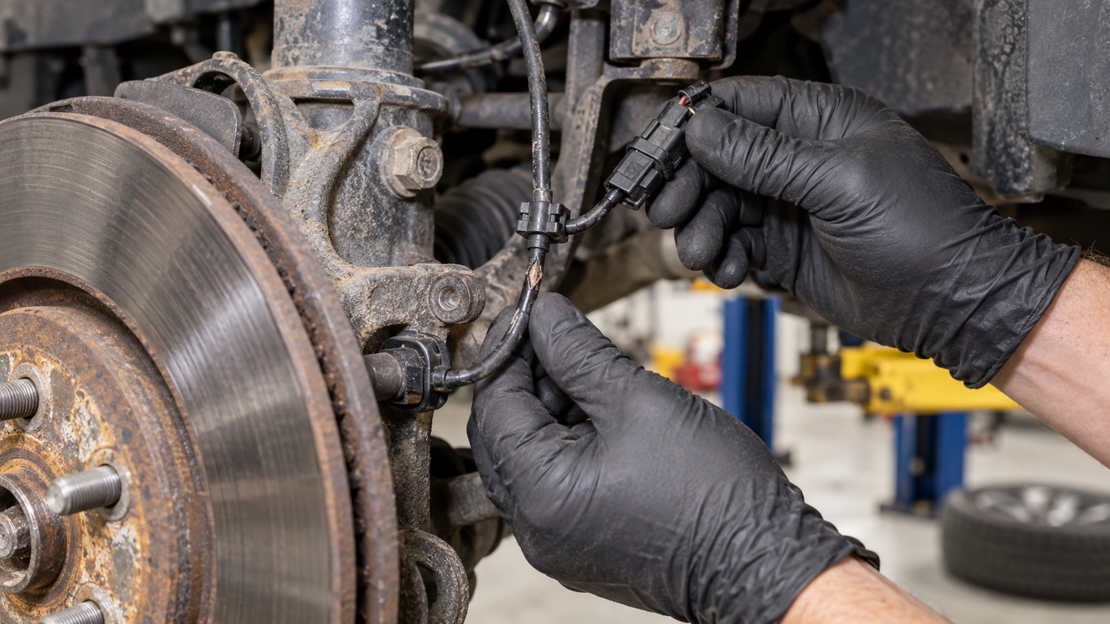
Follow the harness from the sensor to the body-side connector. Look for abrasion where the cable touches the tire, strut, control arm or splash shield. Check every retaining clip and grommet. A cable that was routed on the wrong side of a bracket may be pulled tight at full steering lock or full suspension droop.
Disconnect the plug only with the ignition switched off and according to the service procedure. Inspect for bent terminals, moisture, road salt, dirt, damaged seals, poor terminal retention and previous repair attempts. Do not force oversized meter probes into small terminals; spreading a terminal can create a new intermittent fault.
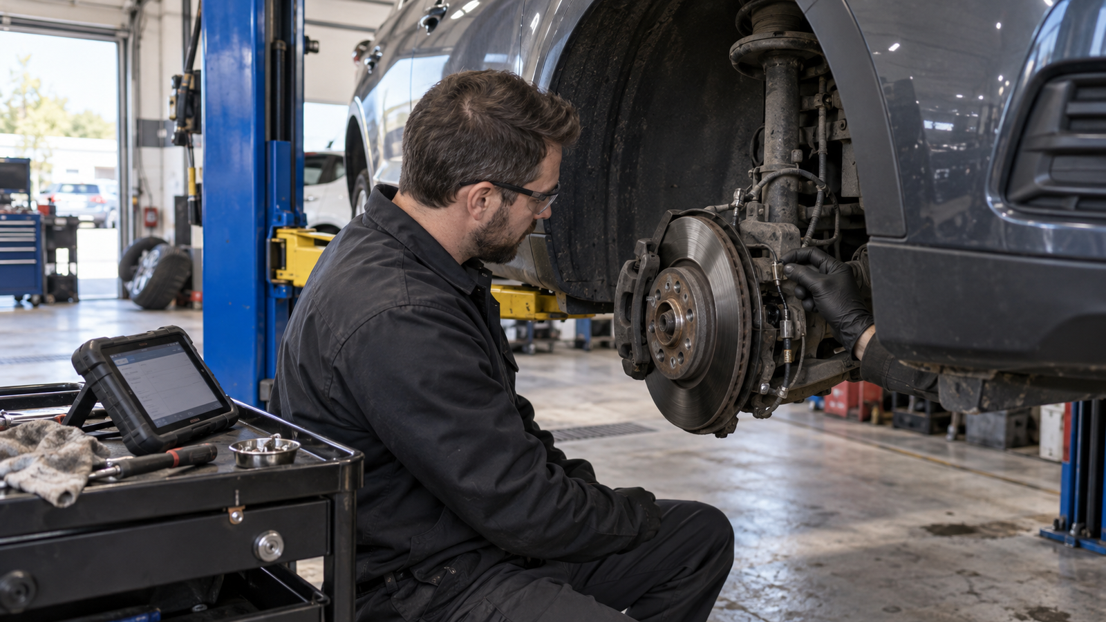
4. Inspect the sensor seat, tone ring and wheel bearing
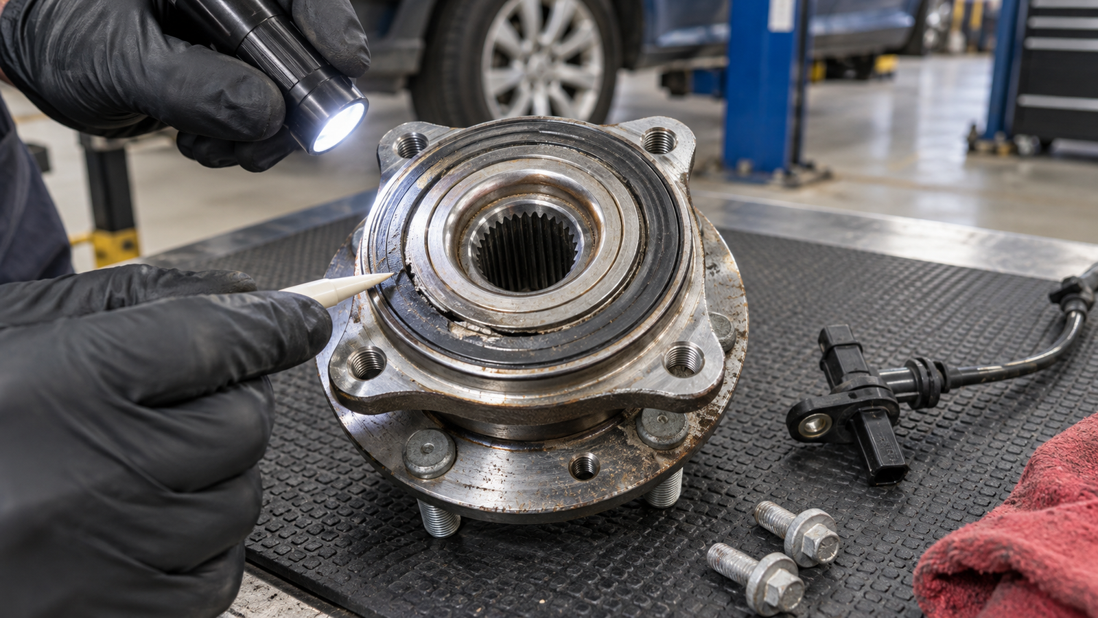
Rust beneath a bolt-in sensor can lift it away from the encoder and weaken the signal. Metallic debris may collect on a magnetic sensor tip. Older exposed tone rings can crack, corrode, lose teeth or move on the axle. Modern magnetic encoder rings can be damaged during bearing handling or installed facing the wrong direction if the bearing design is not followed.
Also check wheel-bearing play and listen for roughness. Movement in the hub can change the sensor gap or damage the encoder. If the signal irregularity repeats at the same point during each revolution, the encoder or tone ring deserves particular attention.
5. Perform electrical tests using the correct specification
Use the vehicle wiring diagram to identify supply, ground and signal circuits. Check at the sensor connector when practical so the complete harness between the control unit and sensor is included. A multimeter can confirm supply voltage and obvious circuit problems; an oscilloscope is better for viewing signal shape, dropouts and disturbances while the wheel turns.
Do not apply external voltage, use a test light, or measure resistance on an active sensor unless the manufacturer explicitly instructs it. A generic numerical value is not reliable across vehicles. The correct waveform, current pattern, supply level and test method depend on the system.
When Does the Sensor Actually Need Replacement?
Replace the wheel speed sensor when testing confirms an internal open or short, no valid output despite correct supply and encoder condition, physical damage to the sensor body, terminal damage that cannot be repaired correctly, or a damaged molded cable that is serviced only with the sensor. If the encoder is integrated into the wheel bearing and is defective, the correct repair may be a bearing or hub assembly instead of a sensor.
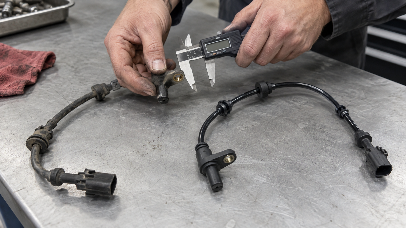
Before ordering, confirm the OE number or application data, axle and corner, connector shape and keying, cable length, mounting-hole position, sensor-head geometry, grommet locations, and whether the sensor is active or passive. Similar-looking parts can have different electronics or cable routing.
Installation and Final Verification
Clean the mounting surface without damaging the encoder, then install the sensor fully seated and tighten its fastener to the specified torque. Route the cable through every original clip and grommet, leaving the correct movement for steering and suspension travel. Keep the harness away from the tire, rotating axle, sharp edges and hot components.
After the repair, clear the stored faults and recheck live data. Carry out an approved road test while comparing the four wheel-speed signals, then scan the vehicle again. A warning light that stays off is encouraging, but matching live data and no returning codes provide a more complete verification.
Frequently Asked Questions
Can a bad ABS sensor make the brake pedal pulse?
Yes. An incorrect low-speed signal can make the control unit believe a wheel is about to lock, causing unwanted ABS operation and pedal pulsation. Similar symptoms can also come from an encoder, air-gap, bearing or wiring problem, so the sensor should be tested rather than assumed faulty.
Can dirt alone cause an ABS warning?
Heavy contamination or metallic debris can interfere with some sensor and encoder arrangements, but cleaning is not a substitute for checking corrosion, physical damage, wiring integrity and live data. If contamination returns, look for the reason.
Will disconnecting the battery reset the ABS light?
It may clear some temporary information on certain vehicles, but it does not repair the cause. Many ABS codes remain stored, and the warning will return when the control unit detects the fault again. Diagnose and correct the problem, then clear codes with an appropriate scan tool if required.
Can I replace only the wheel speed sensor?
Often yes, but not always. Some faults are inside a magnetic encoder integrated into the bearing or hub, and some applications package components differently. Inspect the vehicle and verify the replacement configuration before ordering.
Choose the Correct ABS Sensor Before Installation
A dependable repair begins with a confirmed diagnosis and ends with correct fitment. When requesting a replacement ABS sensor, provide the vehicle details and OE number whenever available. Photos of the original connector, mounting point and full cable routing can also help prevent a mismatch.
Technical references: HELLA Tech World: checking and replacing ABS wheel speed sensors; ATE/Continental wheel speed sensor overview.